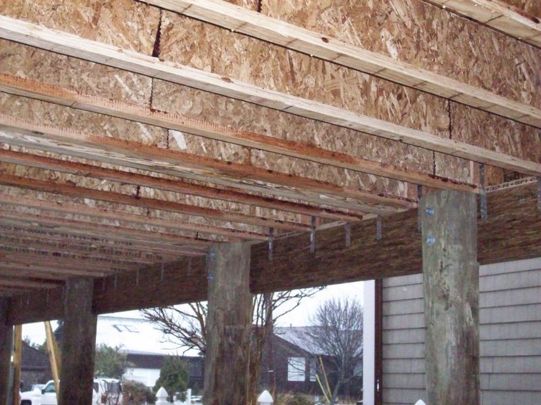
As the snow drifts continue to melt outside my window, builders up and down the northeastern coast are beginning their second construction season since Hurricane Sandy. Bob Kuserk discussed coastal rebuilding in his post in August which focused primarily on the treatment requirements and product options for beams installed below the base flood elevation or in high moisture conditions. In this article, I will focus on the connection details for Trus Joist products used in single-family homes built on pile foundations and will highlight information contained in our new TB-217 Trus Joist Coastal Construction Guide.
The designer of record is responsible for the overall design of a structure built on a pile foundation. These structural systems require that special attention be given to establishing the load path for the proper transfer of gravity (live, snow, and dead) and wind loads (uplift and lateral). Design for seismic loads may also be required in some areas. While Trus Joist is not involved in the overall design of these structural systems, I hope that this information and TB-217 can provide helpful information to designers and builders.
Beam to Pile Connection
Trus Joist beams such as Parallam® Plus PSL, Parallam® PSL, Microllam® LVL and TimberStrand® LSL must be connected to the piles to resist vertical, uplift and lateral loads. Often, these connections are made by bolting the beam to a notched pile. In this case, the vertical (gravity) loads in the beam are transferred to the pile by means of direct bearing of the beam on the pile. TB-217 provides guidelines regarding the percentage of the beam width that must be supported (75%) and the beam bearing capacity for various beams, pile diameters, and bearing widths.
The transfer of uplift and lateral loads from the beam to pile is often accomplished by means of bolted connections. A common detail incorporates two 5/8” diameter bolts. The National Design Specifications for Wood Construction (NDS) provides the criteria for the design of bolted connections and the American Wood Council has online connection calculators. To utilize these NDS provisions, certain material properties are required including Equivalent Specific Gravity (SG) and Modulus of Elasticity (E). Furthermore, bolt capacities must be reduced if required end and edge distances are not maintained. TB-217 provides material properties for Trus Joist beam products, bolt fastener spacing information, and example uplift and lateral load capacity calculations. For example, a 3 ½” x 11 ⅞” Parallam® PSL beam fastened to a 10” Southern Pine Pile with two ⅝” bolts can resist 2,276 lb of uplift load and 2,454 lb of lateral load.
Joist to Beam Connection
The proper design of a cantilevered TJI® joist is important to the integrity of the entire structure. Again, the designer must consider vertical, uplift and lateral loads. Significant shear forces can be created when vertical loads are applied to the ends of cantilevered TJI® joists. Cantilever reinforcement tables contained on pages 10 & 11 of the TJI® Joist Specifier’s Guide (TJ-4000)should be used to verify if joist reinforcement is required for vertical load transfer through the joist to the beam below.
Uplift loads resulting from wind forces on the structure above the floor system are normally transferred from the wall to the TimberStrand® LSL rim board with metal strapping or continuous sheathing. Once the load is in the rim board, it must be transferred into the end of the TJI® joist. The normal rim-to-joist nailing (one nail in each flange) does not provide an adequate connection in most cases. A joist hanger or metal clip can be designed to transfer this load (web stiffeners are required if a metal clip is used). The final uplift load transfer is from the joist to the beam. This is also normally done with a metal strap. The joist to beam uplift strap should be fastened to the web of the joist (with web stiffeners) and not fastened just to the bottom flange of the joist.
The final load transfer to be considered is for lateral loads. Lateral loads in the walls are normally transferred to the floor diaphragm and blocking is used in the floor system to transfer the lateral loads to the parallel beams below. For short cantilevers less than 5” horizontal blocking may be used see cantilever details on page 10 of the TJI® Joist Specifier’s Guide (TJ-4000).
I hope you find this information and the new TB-217 Trus Joist Coastal Construction Guide helpful. If you have any questions about Trus Joist products and how they can be utilized in your next coastal residence, please contact your local Trus Joist representative or contact us.


