By Jerad Bankston, P.E.
The successful design and installation of engineered wood beams such as Microllam® LVL, TimberStrand® LSL and Parallam® PSL goes beyond just looking up a member in a table. Knowing how the beam will be loaded (either side loaded or top loaded) and the overall application of the member will help in determining which product to use to ensure a successful installation.
Beam Connections
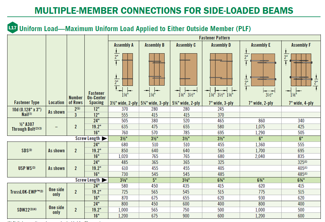
A question we commonly get asked is how to connect a multiple ply beam member. Beam connections are based on how the load is applied (be it top, side or a point load) and the magnitude of the load. Side loads and point loads on beams typically require the most aggressive connection patterns in order to transfer the load to all plies of the beam TJ-9000 provides connection tables for side, top and point loads on beams.
If you are using our single member sizing software, Forte, to size a beam, it now has the functionality to design and report the required connection for a beam based on the load magnitude and how it is applied to the beam. Click here for a video tutorial on using this functionality in Forte.

Side Loads on One Side of Beam
Flush beams with loads applied to only one side need special attention, specifically when the member is 7” wide. Our literature addresses this condition by stating that 7” wide beams should be side-loaded only when loads are applied to both sides of the members (to minimize rotation). The potential for rotation of a beam increases as the load is applied farther away from the centerline of the beam (the wider the beam the more rotation potential). Figure 1 shows how a gap formed between the joists and side loaded flush beam due to the beam rotating under load.

Figure 1. Beam in rotation due to side load
One way to resist rotation is to install an appropriately sized tension strap from the bottom of the joist flange across the bottom of and up the back side of the flush beam. The tension strap will resist rotation and keep the beam and joist together.
Compression Edge Bracing (unbraced length)
When designing a beam, one must also consider how the member will be braced (specifically how the compression edge will be braced) to prevent lateral movement of the beam. For simple span beams, the compression edge is typically on the top of the beam (see Figure 2), however, for multiple span beams, the compression edge changes from top to bottom of beam as it crosses intermediate bearing points (see Figure 3)

Figure 2. Simple Span Beam – Compression edge in blue

Figure 3. Continuous Span Beam Example – Compression edge in blue
Without sufficient bracing, the beam may tend to ‘buckle’ or move laterally, as this simple span porch beam is demonstrating in Figure 4.

Figure 4. Beam buckling under load
Installing pony walls on top of dropped garage door headers is a common practice (see Figure 5). The extent of bracing provided by a pony wall varies based on design elements such as wall height and wall sheathing type. The lateral stability of a dropped beam such as the one below is dependant on the size of the opening, beam size and pony wall height.

Figure 5. Pony wall on top of garage door header
Our TJ-9000 specifiers guide provides guidance how to construct the pony wall and header based on the beam type, size and opening width.
Figure 6 is an example where the pony wall did not provide adequate bracing and the beam began to bow (or buckle) out of the wall.

Figure 6. Bow in beam due to inadequate bracing
This issue could have been resolved at the design stage by specifying the beam to be tight to the double top plates. Alternatively, a more laterally stable solid section header, such as Parallam® PSL or TimberStrand® LSL, could have been used instead of a built up header (See Figure 7).

Figure 7. Header tight to top plates
Multiple span beams, such as this continuous garage door header shown in Figure 8, can become problematic as the wall between the 2 openings typically isn’t sufficient to brace the bottom of the beam.

Figure 8. Continuous garage door header
The result of this continuous garage door header not being adequately braced led to the wall bowing out approximately 1” (see Figure 9).

Figure 9. Wall bowing
The simplest solution to this problem would have been installing the garage door headers as separate (simple span) beams instead of one continuous member. The use of a solid member that didn’t require intermediate bracing would have been a solution as well.
Consideration of how a beam will be loaded and how the beam will be braced by the surrounding structure will help determine the appropriate product for the application. If you should have questions on your next design, feel free to contact our technical support team at 888-453-8358 or email techsupport@weyerhaeuser.com.
JERAD BANKSTON, P.E.

Jerad Bankston, P.E. is a Weyerhaeuser engineer supporting Trus Joist Engineered Wood Products who is based out of St. Paul, Minnesota. During his 14+ years with Weyerhaeuser, Jerad has provided technical support and training for residential, multifamily and industrial applications.


